Tooling & Mold Engineering
Extrusion Dies Aluminum, Rubber & Silicone Profile Tooling
Custom extrusion die engineering for continuous profiles: structural aluminum rails, thermal extrusions, rubber seals and silicone gaskets. We design dies and mandrels, run prototype trials, validate vacuum sizing and provide lifecycle support including maintenance, spare parts and downstream cut/finish operations.
- Die CAD, mandrel & feed design, vacuum sizing and co‑extrusion tooling
- Prototype die trials, die iteration, and scale‑up to hardened production dies
- Spare lands, PM plans and quick repair strategies to protect production uptime
Aluminum Die — Structural & Thermal Profiles
Rubber & Silicone Dies Seals & Gaskets
Co‑Extrusion & Multi‑Material Dies
Aluminum Extrusion Dies
We design dies for 6061/6063 profiles including thermal rails, frame sections and fins. Die design accounts for cross‑section complexity, wall thickness balance, internal channels, billets, and press capabilities. We collaborate with press suppliers to match die land, billet preheat, and extrusion speed to minimize cracking and maintain dimensional tolerances.
Capabilities & features
- Custom die tooling with removable inserts and replaceable lands
- Mandrel / spider support for hollow profiles and internal channels
- Die balancing, feeder design and scrap/trim solutions for minimal waste
- Die tryout, straightening, stretching and aging process support

Rubber & Silicone Extrusion Dies
Dies for elastomer profiles are designed with mandrels, vacuum sizing and cooling to control dimensions and die swell. We produce dies for EPDM, NBR, FKM, VMQ/silicone and TPE materials. Special tooling includes vacuum ports, sizing calibrators and run‑out ovens for vulcanization and post‑cure where required.
Design focus
- Sizing mandrels and vacuum channels for tight section tolerances
- Co‑extrusion die blocks for dual‑durometer or bonded profiles
- Material feeding and screw/die compatibility for continuous runs
Co‑Extrusion & Multi‑Material Dies
Co‑extrusion tooling bonds two or more materials in a single profile (for example, soft sealing lip onto a rigid carrier). Die design ensures proper flow distribution, adhesion interface geometry and thermal compatibility. We validate adhesion through trials and specify compatible material pairings.
Typical uses
Rigid carrier + soft seal for snap‑in installation
Color or functional overcoat on a base profile
Integrated gasket + extrusion for simplified assembly
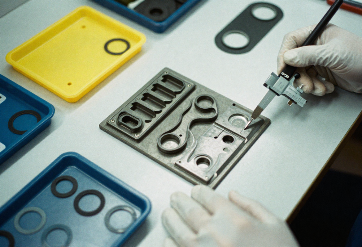
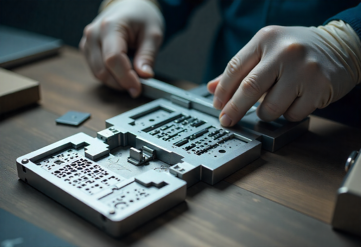
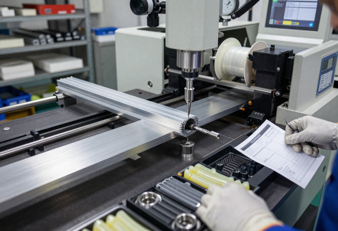
Die Design, Simulation & Tryout
Die design uses CAD/CAM, flow simulation and mandrel FEM to predict dimensional outcomes and stress. For aluminum we analyze billet flow, fill, and die wear. For elastomers we model die swell and vacuum sizing behavior. Prototype tryout includes sectional sampling, dimensional checks and iterative die rework to reach target tolerances.
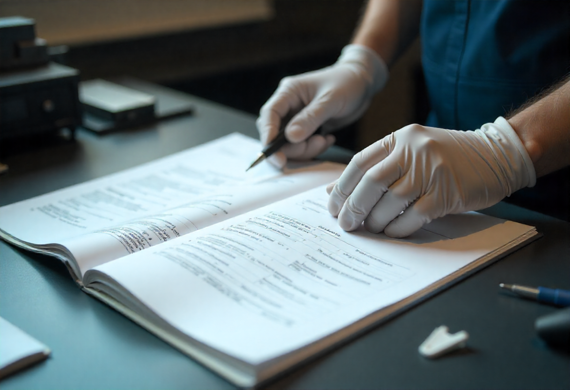
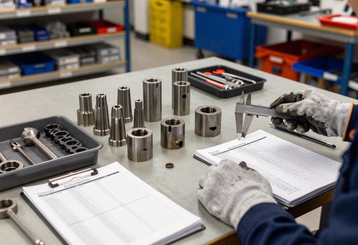
Tryout deliverables
- Sample coils or cut profiles for dimensional inspection
- Die acceptance reports, mandrel condition checks, and recommended PM intervals
- Die iteration cycle notes and final die set documentation for production handover
Die Materials, Hardening & Surface Treatments
Die block materials and coatings are chosen for abrasion resistance, corrosion protection and thermal stability. Common choices include tool steels (A2, D2) for rubber dies and hardened steels with nitriding for aluminum press tooling. Surface treatments (nickel plating of channels, PVD/TiN) extend service life.
Rubber dies
Hardened & plated steel with precision mandrel bores and vacuum ports
Aluminum die plates
Hardened inserts for lips/lands; replaceable inserts to reduce downtime
Coatings
Nickel plating, chrome, TiN where wear and corrosion expected
Heat treatment
Selected by alloy and expected shot life / abrasive exposure
Maintenance, Spares & Rapid Repair
Planned maintenance prevents unplanned stops. We recommend spare lands, mandrels or insert sets for critical profiles and provide refurbishment services including regrinding, replating and bore rework. Rapid repair lanes and spare distribution options are available to meet uptime goals.
Recommended program elements
- Spare inserts and mandrels for quick changeover
- Scheduled inspection by shot count or runtime
- Onsite or depot repair SLA options for critical lines
Secondary Operations & Downstream Integration
After extrusion we provide cut‑to‑length lines, CNC machining of endfaces, drilling, tap inserts, coining or crimping operations, vulcanization ovens for elastomers and inline inspection. We can supply kitted, cut and finished lengths ready for assembly.
Automation & tooling
- Automatic length cutting, end‑machining and chamfering
- Coiling, spooling and packaging for continuous runs
- Post‑vulcanize ovens and controlled cool down for elastomers
Representative Specs & Lead Times
| Parameter | Range | Notes |
|---|---|---|
| Materials | Aluminum 6061/6063; EPDM, Silicone, NBR, FKM, TPU | Select for mechanical, thermal and chemical environment |
| Surface finish | Anodize, powder coat, mill finish | Anodize recommended for corrosion resistance and aesthetics |
| Co-extrusion | Yes | Soft + rigid combinations for integrated seals and carriers |
| Prototype lead time | 2–4 weeks | Dependent on die complexity and material |
Representative Projects

Finned Aluminum Thermal Rail
Custom die with integrated internal channel for coolant, produced as an extruded rail then CNC‑machined to final tolerances; anodized finish and kitted lengths delivered.

Co‑Extruded Silicone Seal on Rigid Carrier
Two‑material die combining rigid PVC carrier and LSR silicone lip — validated adhesion and vacuum sizing to control seal geometry over length.
Frequently Asked Questions
How do you control die swell in elastomer extrusions?
We design mandrels and vacuum sizing stages, tune die land length and use process control for temperature and draw speed. Prototyping verifies final dimensions and guides die adjustments.
Can I co‑extrude dissimilar materials like silicone onto a metal carrier?
Yes — co‑extrusion is commonly used to bond soft seals to rigid carriers. We validate material compatibility, adhesion methods (chemical primers or mechanical undercuts) and die geometry in prototyping.
What information do you need to quote a die?
Provide a cross‑section (DXF/DWG or STEP), target material(s), expected volumes, length tolerances, surface finish and any downstream operations (cut, machine, post‑cure). Photos of similar parts help speed assessment.
Do you offer die leasing or shared ownership?
Yes — we offer tooling ownership models including lease, shared ownership and amortization options to reduce customer upfront CAPEX. Ask for options during RFQ.
Start Your Extrusion Die Project
Upload your profile cross‑section or STEP file, material choice and target volumes. We’ll return a die recommendation, prototype plan and lead time estimate — typically within 24 business hours.

