Skived Heat Sinks — Ultra‑High Fin Density, Low Thermal Resistance
Skived heat sinks deliver industry‑leading fin density and thermal performance by machining fins from a solid billet. We engineer fin geometry, base thickness and fin height for optimized spreading, pressure drop and manufacturability—then validate with thermal testing and production‑grade quality controls.
⚙️ Typical materials: 6061 / 6063 aluminum 🟤 Copper bases (high conductivity)
🛡️ Optional anodize or plating for corrosion resistance & appearance
Validated Builds • FAI/PPAP • Process Windows
Why Choose Skived Heat Sinks?
Skiving creates fins by cutting from a single block, producing seamless fins with excellent thermal contact to the base and very high fin densities (often > 80 fins per inch). Compared with bonded or extruded fins, skived fins offer lower thermal resistance per unit volume, better mechanical robustness, and flexible fin geometry for tailored pressure‑drop vs ΔT tradeoffs.

High Fin Density & Thermal Efficiency
Fin pitch and height are tuned for your heat flux and available flow, delivering lower RθJA and improved hotspot spreading.

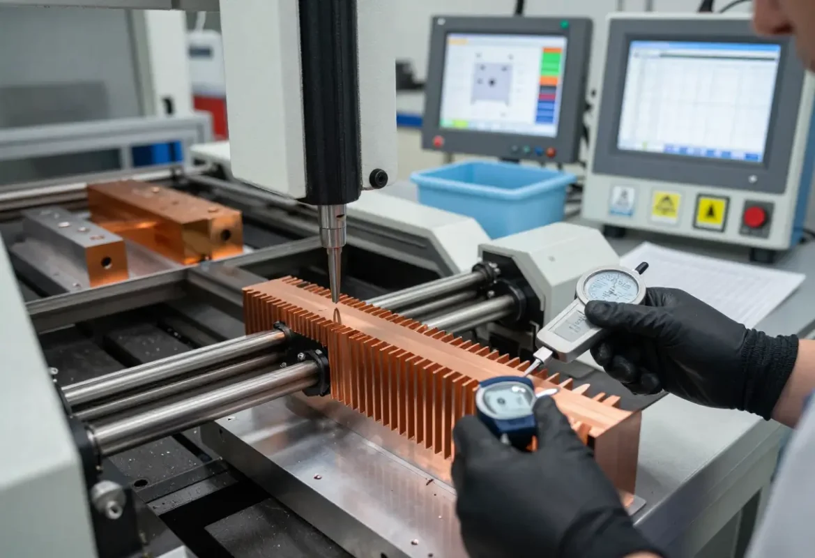
Low Thermal Resistance & Robust Bond
Fins are integral to the base (not bonded), giving superior thermal conduction and durability under vibration and thermal cycling.

Flexible Geometry & Low Profile Designs
Skiving supports thin fins, variable fin height, stepped bases and integrated mounting features for form‑fit integration.
Manufacturing Process
We start with billet material sized to your envelope. Skiving cuts continuous fins from the block with controlled shear to maintain fin straightness and surface finish. Subsequent operations include precision machining of mounting faces, holes and thermal interfaces, anodize or plating, and final cleaning/QA.
Process controls
Tool wear monitoring, fin straightness checks, base flatness CMM, and pressure‑drop verification are part of standard process control. Typical production flows include inline leak/pressure testing when integrated with liquid cold plates.
Materials & Coatings
Common base and fin materials: aluminum (preferred for weight and cost) and copper (when conductivity is paramount). Coating options include hard anodize, conversion coatings and selective plating where corrosion resistance or dielectric isolation is required.
Corrosion & environment
We assess coolant chemistry, ambient exposure and galvanic concerns to recommend barrier coatings or mixed‑metal mitigation strategies.
Fin Geometry & Typical Specifications
Below are representative geometry ranges—final values are tuned to your airflow, acoustic and ΔT targets.
Fin Pitch
0.2–1.5 mm (very fine to coarse depending on air flow and dust tolerance)
Fin Height
5–50 mm (matched to thermal resistance and device clearance)
Fin Thickness
0.08–0.5 mm (tradeoff between fin stiffness and thermal path)
| Parameter | Range | Notes |
|---|---|---|
| Fin Density | 10–120 fins/inch | Higher density for low air speed, higher pressure drop; cleanable designs for dusty environments |
| Base Thickness | 3–12 mm | Thicker base improves spreading and mounting stiffness |
| Material | Al 6061/6063, Cu | Aluminum common; copper for high conductivity needs |
Thermal Performance & CFD Correlation
We pair CFD and lumped thermal models with prototype testing. Typical deliverables include ΔT vs airflow curves, pressure‑drop vs flow, and thermal resistance (RθJA) estimates correlated to measured prototypes.
Performance depends on flow regime, fin geometry and module layout. We provide sensitivity analyses to show how Rθ changes with fin pitch and base thickness to guide tradeoff decisions.
Testing & Validation
Prototype characterization covers steady‑state thermal maps, transient response, airflow vs ΔT curves and vibration testing for mechanical robustness. We also test for corrosion resistance and surface finish adhesion as required.
Typical test reports
Thermal test report, pressure‑drop curves, vibration & shock summary, surface & coating certificates, and FAI dimensional report.
Applications

Power Electronics & Inverters
High heat flux dissipation in inverters, OBCs and DC‑DC modules where compact, low‑profile sinks are needed.

Telecom & Datacom
High-density racks and line cards requiring tight thermal control with limited airflow.

Industrial & Specialty Systems
Controlled environments, test equipment and power supplies where long life and reliability are critical.
Ready to Specify Your Skived Heat Sink?
Share your power map, envelope and airflow constraints. We’ll respond with feasibility notes, fin geometry options and a path from prototype to production.