
Our Manufacturing Standards
Xometry has developed a comprehensive set of Design Guides to assist you in optimizing your design for the manufacturing method selected; please consult them for critical tips and tricks.
All uploads are secure and confidential.

Workmanship Standards
Orders with Xometry will meet the minimum workmanship standards outlined below (as applicable to the process). If your project requires a level of workmanship that goes beyond the standards listed below, please clearly list the requirement in your engineering drawings, purchase orders, or specifications.
Finished Surfaces Cosmetics
- Paint coverage on surfaces will be uniform, including adjacent materials of assemblies.
- Finished surfaces will be free of defects, including chips, scrapes, or other damage.
- Parts made with Sheet Cutting and Sheet Metal Fabrication have different cosmetics standards. Please see their sections below for details.
Mill Steps, Tooling, and Chatter
- Tool marks on as-milled surfaces will be free of defects, including burrs, chatter, tool gauges, and will meet surface roughness specifications.
- Indicated critical surfaces will be free of mill steps and marks across the entire surface.
- Milled surfaces will meet surface roughness specifications.
Chips, Burrs, and Sharp Edges
- All exposed edges will be free of burrs, sharp edges, and metal slivers.*
- *Parts made with Sheet Cutting are not deburred unless specified through a selected finish.
Foreign Object Debris (FOD)
- Surfaces will be free of cutting fluid, metal chips, foreign objects, and other debris.
Threads
- Threads will be fully formed and cut to specified size and class indicated in provided drawings.
- Threads will be free of defects, notable damage, and contamination.
Plated Surfaces
- Plated surfaces will be uniform, including adjacent surfaces of assemblies.
- Plated surfaces will be free of machining marks, scratches, pits, protrusions, or visible bare metal.
- Some minor defects may be permissible in certain situations if they do not compromise the protective finish.
Weld Joints
- Weld joints are performed as indicated in the customer-provided drawing.
- Welds without specific requirements are cleaned to remove slag or other surface contamination.
- Weld joints will not be painted until the welding has been completed and the weld has passed inspection.
Countersinks
- Countersinks shall be round and made to print specifications and allow the proper designed fit with the mating screw.
- Countersinks will be free of burrs, chatter, or other tooling defects.
Painted Surfaces
- Painted surfaces shall be consistent and continuous in the finish.
- Painted surfaces shall be free of visible machining marks, scratches, abrasions, dust particles, fisheyes, orange peel, or bare metal.
- Painted surfaces should be reviewed against this standard at a distance of 18″ at 1X magnification.

CNC Machining and Turning
- For features of size (Length, width, height, diameter) and location (position, concentricity, symmetry) +/- 0.005” (metals) or +/- 0.010 (plastics and composites) following ISO 2768 unless otherwise specified.
- As machined surface finish is 125 Ra or better. Machine tool marks may leave a swirl-like pattern.
- Sharp edges will be broken and deburred by default. Critical edges that must be left sharp should be noted and specified on a print.
- Clear or transparent plastics will be matte or have translucent swirl marks on any machined face. Bead blasting will leave a frosted finish on clear plastics.
- Xometry cannot guarantee tolerances on foam or similar compressible materials.
- General tolerances for orientation and form features are outlined below unless we have agreed to other tolerances in your Quote. These features include parallelism, perpendicularity, cylindricity, concentricity, flatness, circularity, and straightness.
CNC Orientation and Form General Tolerances for Metals
| Part Length | Orientation and Form Tolerance (inch) | Angularity Tolerance (degree) |
|---|---|---|
| 0 to 12" | .005" | 0.5° |
| 12" to 24" | .010" | 0.5° |
| 24" - 36" | 1/64" (.016") | 1° |
| 36" - 60" | 1/32" (.031") | 1° |
| Over 60" | 1/16" (.063") | 1° |
Form tolerances apply to metal machined components. Plastic and composite materials are typically double the tolerance amount for metals.
Learn More About CNC Machining

NEW!

Die Casting
- Typical mold machined tolerances are +/- 0.010" when machining the mold and an additional +/- 0.001" per in. when calculating shrink rate.
- Tighter as-molded tolerances can be requested and may increase the cost of tooling. Additionally, many tight tolerances require the mold to be manufactured, sampled, and groomed. Xometry will mill to a steel-safe condition on critical features.
- Critical toleranced features and surface finishes may require post-machining and should be noted in the quote prior to order. Post-machined features will follow Xometry’s CNC manufacturing standards.
- Xometry will produce die cast components according to the net-shape (as-cast) model provided by the customer. These models must contain appropriate material for any additional post-processing efforts, such as post-machining. It is recommended to provide the as-cast 3D model as well as the final model with any accompanying technical drawings.
- Part-to-part repeatability is typically under +/- 0.004".
- As-cast surface finish is typically 64 μin. The standard finish for die-casting is as-cast and cannot guarantee a specific Ra value without additional processing.
- The lead time is for the first article shipment (T1 shipment). The remaining production time is confirmed after the first article approval.
- Typical first article shipments are five pieces but may vary based on size, origin, and material.
- All quotes are based upon the assumption that designs have an adequate draft, radii, and coring for manufacturability.
- Cores, side actions, and tooling strategy are determined by Xometry unless explicitly discussed.
- Gating, ejection, knit lines, and parting lines are at the discretion of Xometry unless explicitly discussed.
- Parting line(s) on die cast parts will be visible as a thin ridge traveling across the part.
- Cast parts may have one or many gate vestiges, which are trimmed, sheared, or ground off.
- Ejector pin marks will be present on die cast parts, resembling round flats.
Learn More About Die Casting
")

Plastic Injection Molding
- Typical mold machined tolerances are +/- 0.005" when machining the mold and an additional +/- 0.002" per in. when calculating for shrink rate.
- Tighter tolerances can be requested and may increase the cost of tooling. Additionally, many tight tolerances require the mold to be manufactured, sampled, and groomed. Xometry will mill to a steel-safe condition on critical features.
- Part-to-part repeatability is typically under +/- 0.004".
- Lead time stated is for first article shipment. Remaining production time is confirmed after first article approval.
- Typical first article shipments are 10 pieces but may vary based on size, origin, and material.
- Xometry cannot guarantee a perfect color match per Pantone color.
- All quotes are based upon the assumption that designs have an adequate draft, radii, and coring for manufacturability.
- Cores, side actions, and tooling strategy are determined by Xometry unless explicitly discussed.
- Gating, ejection, knit lines and parting lines are at the discretion of Xometry unless explicitly discussed.
Learn More About Injection Molding
")
NEW!
Metal Extrusion
- All quotes are based upon the assumption that designs have adequate wall thicknesses, radii, and feature sets designed for manufacturability in this process.
- Critical-to-function tolerances should be discussed at the time of quoting to ensure that tooling strategy, check gages (if applicable), and other quality controls are encompassed in the quote.
- Linear cross-section dimensions are +/- 0.010", or +/- 0.006” per inch, whichever is greater, excluding wall thickness.
- Wall thickness is +/- 10% of the specified dimension.
- Cross-section angularity for external corners is +/- 1 degree, and +/- 2 degrees for internal angles.
- Critical toleranced features and surface finishes may require post-machining and should be noted in the quote before order. Post-machined features will follow Xometry’s CNC manufacturing standards.
- Customer-provided models must contain appropriate material for additional post-processing efforts, such as post-machining. Xometry recommends providing the extruded 3D and final models with any accompanying technical drawings.
- The surface roughness of as-extruded features is 125 μin Ra.
- Twist not to exceed 0.5 degrees per 12” length is typical.
- Straightness not to exceed 0.0125” per 12” length.
- Sharp corners will have a radius of at least 0.016”.
- Corner radii up to 0.188” will have a +/- 0.016” standard tolerance. Any radii over 0.188” will have a +/- 10% tolerance.
Learn More About Metal Extrusion

NEW!

Plastic Extrusion
- All quotes are based upon the assumption that designs have adequate wall thicknesses, radii, and feature sets designed for manufacturability in this process.
- Critical-to-function tolerances should be discussed at the time of quoting to ensure that tooling strategy, check gages (if applicable), and other quality controls are encompassed in the quote.
- Critical toleranced features and surface finishes may require post-machining and should be noted in the quote before ordering. Post-machined features will follow Xometry’s CNC manufacturing standards for plastics.
- Customer-provided models must contain appropriate material for additional post-processing efforts, such as post-machining. Xometry recommends providing the extruded 3D and final models with any accompanying technical drawings.
- Wall thickness is typically +/- 10% of the specified dimension.
- Angularity is typically +/- 3 degrees for rigid materials and +/- 5 degrees for flexible materials.
- Twist typically does not to exceed 0.5 degrees per 12” length. Camber and bow not to exceed 0.025” per 12” length.
- The surface roughness of plastic extrusions will be 125 μin Ra or better.
- Sharp corners will have a radius of at least 0.016”.
- Lumens within extruded tubes will be limited to four unless otherwise agreed upon.
- Dimensions inside of hollows are difficult to control and will require tolerances considerably greater than the standard tolerances.
Standard Plastic Extrusion Tolerances By Feature Size
| Size of Dimension | Standard Tolerance * |
|---|---|
| < 0.125” | ± 0.010” |
| 0.125” - 0.500” | ± 0.020” |
| 0.500” - 1.00” | ± 0.030” |
| 1.00” - 1.50” | ± 0.035” |
| 1.50” - 2.00” | ± 0.040” |
| 2.00” - 3.00” | ± 0.045” |
| 3.00” - 4.00” | ± 0.065” |
| 4.00” - 5.00” | ± 0.085” |
| 5.00” - 7.00” | ± 0.100” |
| 7.00” - 10.00” | ± 0.125” |
* General tolerances strongly depend on the material extruded and cross-section complexity. Specialized tooling can be used to obtain tighter tolerances than those listed above.
Learn More About Plastic Extrusion
")

Sheet Cutting Service
- Thickness tolerances are independent of cutting tolerances, as they rely on the raw stock material’s tolerance range.
- Edge to edge tolerances is +/- 0.010” nominal on the top face of the plate/sheet.
- Thicker materials may have a tolerance deviation on the bottom face due to tapers inherent in laser cutting, waterjet cutting.
- Xometry cannot guarantee flatness call outs for sheet cut materials except on ground stock or tooling plate (e. g. MIC6).
- Holes of 0.100” or smaller in diameter may be slightly larger on the top face than standard tolerances due to the cutter piercing the material near the hole's cut line.
- A small bump or divot in the material or a different edge condition may be present at the lead-in and lead-out in a cutting profile.
- Pre-finished or textured sheets, such as brushed or polished stock may have only one side with the cosmetic finish.
- Protective film may be shipped on cut products to prevent damage of cosmetic finishes.
- The edge condition of sheet cut materials will have vertical striations versus smooth edges. This affects the transparency of edges on clear plastics cut with waterjet.
- Some cut materials may show a small halo discoloration from backsplash (waterjet) or overspray near the cut edges (laser).
For further information regarding de-tabbing, deburr, and surface finishing, please refer to our FAQ page.
Learn More about Sheet Cutting (Laser and Waterjet)
")

Sheet Metal Fabrication
- See Sheet Cutting standards for edge-to-edge and other cutting tolerances over flat surfaces.
- Sharp edges will be broken and deburred by default. Critical edges that must be left sharp should be noted and specified on a drawing.
- Specific sheet metal designs require custom tooling and will be flagged for a manual quote: hems, curled flanges and rolled sheets, stamped parts, and welded assemblies. If your part includes these features, please allow our manual quote team to review and provide you with an accurate cost and lead time.
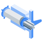
Sheet Metal Standard Dimensional Tolerances
These are the Xometry’s standard tolerances when no other tolerances are specified. Tighter tolerances are available with manual review when you provide a dimensioned drawing with tolerances.
A – ± 0.015″ Edge to bend
B – ± 0.030″ Across bend
C – Relies on the raw stock’s tolerances based upon material and thickness
D – ± 0.015″ Bend to hole or internal cut feature
E – ± 0.030″ Overall edge-to-edge on formed part
F – ± 1 Degree Bend angle
G – ± 0.030″ Edge-to-feature over multiple formed surfaces
H – ± 0.010″ Feature edge-to-edge over the same surface over the top of the cut face
Learn More about Sheet Metal
")
NEW!

Metal Stamping
- All quotes are based upon the assumption that designs have an adequate draft, radii, relief cuts, and feature sets for manufacturability in this process.
- Critical-to-function tolerances should be discussed at the time of quoting to ensure that tooling strategy, check gages (if applicable), and other quality controls are encompassed in the quote.
- Raw material such as coiled strip is not flat by nature and can show through on flat stamped or coined components.
- Dimensions apply to the inside of the formed feature.
- Angular tolerances of +/- 1 degree are typical.
- Stamped parts will be free of splits and other forming defects.
- Punch and die-cut features, such as edges, will have a straight wall with a small burr on the bottom edge approximately ¼ to ⅓ down the wall thickness.
- Large burrs and tabs will be removed, but parts are not manually fully deburred before shipment with a standard, as-cut finish selection.
- Linear dimensions for internal holes will be measured at the shear, or smallest portion of a cut feature.
- Tooling marks are a normal part of the metal forming process. Marks can be minimized with secondary processing or tooling strategy. It is important to identify cosmetic features with Xometry during the quoting or kick-off phase.
- The material thickness will vary across formed and drawn features.
- Part-to-part repeatability is typically under +/- 0.004" (+/- 0.002” typical).
Learn More About Stamping
")
NEW!
Laser Tube Cutting
- Cut edges will be normal-to-surface as a default. Normal-to-edge cuts will require agreement at the time of order.
- Thickness tolerances are independent of cutting tolerances, as they rely on the raw stock material’s tolerance range.
- Edge-to-edge tolerances of laser cut features are +/- .010” nominal on the inner face of the tube.
- Holes of .100” or smaller in diameter may be slightly larger than standard tolerances due to material pierce happening near the hole’s profile. Holes that require drilling or machining precision require a manual review during quoting.
- A small bump of material or a different edge condition may be present at the lead-in and lead-out in a cutting profile.
- Large burrs and tabs will be removed, but parts are not manually fully deburred before shipment with a standard, as-cut finish selection.
- Some cut materials may show a small halo discoloration from the backsplash or overspray near or across from the cut edges.
Learn More About Laser Tube Cutting

NEW!
Tube Bending
- Cut edges will be normal-to-surface as a default. Normal-to-edge cuts will require agreement at the time of order.
- Tube bending manufacturing standards reflect rotary drawn with or without mandrel bending techniques depending on the project's needs. Compression bending, roll bending, freeform, or other bending methods will require functional specifications agreed upon at the time of order.
- Tube thickness tolerances are independent of cutting tolerances, as they rely on the tolerance range of the raw stock material.
- The Center line radius (CLR) will be matched to the closest common tooling, not to exceed +/- .25" of the design.
- Wall thickness deviation at bends is normal, as it will stretch on the outer (extrados) of the bend and compress on the inside of the bend (intrados). Certain bending processes will stretch more and are also dependent on material grade.
- Wall thickness deviation at bends is normal, as it will stretch on the outer (extrados) of the bend and compress on the inside of the bend (intrados). Certain bending processes will stretch more and are also dependent on material grade.
- Edge-to-edge tolerances of laser cut features are +/- .010” nominal on the inner face of the tube.
- Tolerances are cumulative across bent tube features.
- Bend angle +/- 1°
- Rotation +/- 2°
- Angularity: +/- 2 degrees.
- Segment Length +/- .030”
- The overall tube sheath envelope (best fit) tolerance is not to exceed +/- .125”.
- Tube end point tolerance is +/- .063” to ensure fit and assembly.
- Ovality at a tube bend should not exceed 10% (5% to 8% typical) of averaged measured OD vs. nominal OD. The equation for ovality is ((Actual Max Ø - Actual Min Ø) ÷ Nominal Ø) x 100.
- Holes of .100” or smaller in diameter may be slightly larger than standard tolerances due to material pierce happening near the hole’s profile. Holes that require drilling or machining precision require a manual review during quoting.
- A small bump of material or a different edge condition may be present at the lead-in and lead-out in a cutting profile.
- Large burrs and tabs will be removed, but parts are not manually fully deburred before shipment with a standard, as-cut finish selection.
- Some cut materials may show a small halo discoloration from the backsplash or overspray near the cut edges.
- Die marks are common along the arc length of the bend and are assumed acceptable under 1/32”. Any sharp edges shall be removed and blended into adjacent surfaces.
- Straight lengths between bends may show some minimal “out-of-round” distortion due to the manufacturing process. This situation might also be seen if a tube end is less than nominal OD + 1” from the trailing bend tangent.
- All tube bends will be free of wrinkles and creases.
- Tube discoloration may be present from local heat correction of bend angles. Localized correction for minor dimensional deviations is acceptable.
- The tube ID will be free of any debris, metal shavings, dirt, etc. Tube ends may be capped or covered before shipment to prevent any foreign materials from entering.
- Unless otherwise specified, tubes will be shipped without external preservation or paint.
Learn More About Tube Bending


Urethane Casting
- Tolearance are +/- 0.010” or +/- 0.003” per inch, whichever is larger, is typical. Irregular or overly-thick geometries may cause deviances or deflection due to shrinkage.
- A shrinkage rate of +0.15% can be expected due to thermal expansion of the liquid, and the response of the flexible mold.
- Surface finish is externally smoothed to a satin or matte surface. Grow lines may be present on internal or difficult-to-access features. Polishing or custom finishes must be clearly defined and agreed upon at the point of order.
- Sharp corners and text may appear slightly rounded.
Learn More About Urethane Casting
")

Metal Binder Jetting 3D Printing
- Metal binder jet parts are made in ExOne 420i metal, which is roughly 60% 420 stainless steel and 40% bronze infiltration.
- Depending on the part’s size and geometry, parts may shrink 0.8% - 2.5% after processing.
- Internal geometries, such as slots and holes, may shrink as much as 5%.
- Xometry does not guarantee tolerances on the first order of a new design.
- Improved tolerances may be possible with a manual quote review, after successful completion of a prototype build, and must be approved on a case-by-case basis.
- Metal binder jet machines print in layers of 0.004” (0.1 mm) and parts are typically oriented in the lowest Z direction.
- Parts with features below 0.03” (0.75 mm) will need to be thickened for successful processing. It is recommended the minimum feature size be above 0.04" (1 mm).
- Modeled threads or precision features may have limited functionality as printed.
- Tumble polished parts may have trapped walnut media between thin gaps or text features.
- General tolerances apply before secondary finishing or post-processing unless otherwise specified.
Learn More about Metal Binder Jetting
 (1)")

Carbon DLS™ 3D Printing
- +/- 0.003” for the first inch is typical, plus +/- 0.010” for every inch thereafter. However, Xometry does not guarantee tolerances on the first order of a new design. Tolerance expectations can vary across materials (e.g., elastomeric versus rigid). See the table below, General Accuracy for DLS Prints, for material-specific information.
- Stresses during build, support strategy, and other geometry considerations may cause deviation in tolerances and flatness.
- Parts with thicker geometries, flat or broad parts, and parts with uneven wall thicknesses may be prone to significant deviations or warp.
- Modeled threads or precision features may have limited functionality as printed. Tapping or the addition of threaded inserts is recommended for best function.
- Improved tolerances may be possible with a manual quote review, after successful completion of a prototype build, and must be approved on a case-by-case basis.
- General tolerances apply before secondary finishing or post-processing unless otherwise specified.
- Areas with support structure may show raised bumps where the structure was removed. In certain materials, like EPX, SIL, and EPU, supported areas may be more visible because post-processing options are limited.
| Resin | General Accuracy | Production Repeatability |
|---|---|---|
| UMA 90 | ±0.003 in + 0.001 in/in | ±0.002 in |
| RPU 70 | ±0.003 in + 0.011 in/in | ±0.002 in |
| FPU 50 | ±0.002 in + 0.011 in/in | ±0.002 in |
| EPX 82 | ±0.003 in + 0.013 in/in | ±0.002 in |
| EPU 40 | ±0.003 in + 0.010 in/in | ±0.003 in |
| SIL 30 | ±0.005 in + 0.018 in/in | ±0.003 in |
Source: Carbon3D
Learn More about Carbon DLS™
")

DMLS 3D Printing
- +/- 0.005” for the first inch is typical, plus +/- 0.002” for every inch thereafter. However, Xometry does not guarantee tolerances on the first order of a new design. Tolerance expectations can vary across different materials (e.g. stainless steel versus aluminum).
- Internal stresses during build, support strategy, and other geometry considerations may cause deviation in tolerances and flatness.
- Items and geometries which require strict flatness are not a good fit for this process.
- Modeled threads or precision features may have limited functionality as printed. Tapping or the addition of threaded inserts is recommended for best function.
- Expected surface roughness is 150-400 µin RA, depending on build orientation and material used for the build.
- General tolerances apply before secondary finishing or post-processing unless otherwise specified.
Learn More About DMLS
")

FDM 3D Printing
- +/- a single build layer thickness for the first inch and +/- .002” for every inch thereafter.
- 0.010” layer thickness is used for parts fitting within a 14” X 16” footprint (Fortus 450)
- 0.013” layer thickness is used for parts exceeding 14” X 16” footprint (Fortus 900)
- 0.008" layer thickness used for Prototyping PLA (9.8" x 8.2" x 8.2", Prusa MK3S/MK4 or Bambu Lab X1C desktop FFF)
- Guaranteed tolerances may be possible with a manual quote review, and must be approved on a case-by-case basis.
- Xometry chooses optimal build orientation taking into consideration overall surface quality and minimum build time unless otherwise specified.
- Minimum resolvable feature size, including positive text features, is at least 0.035” (0.045” or greater is safest).
- Modeled threads or precision features may have limited functionality as printed. Tapping or the addition of threaded inserts is recommended for best function.
- Holes smaller than 0.040", horizontal holes and protrusions will build slightly oblong due to stair stepping from layers.
- General tolerances apply before secondary finishing or post-processing unless otherwise specified.
Learn More About FDM
")
HP MJF 3D Printing
- HP MJF parts are typically built at an angle for a more consistent surface finish. The tolearance table below depicts typical tolerances based on part size.
- Parts with thicker geometries, flat or broad parts (>7”), and parts with uneven wall thicknesses will be prone to significant deviations or warp due to variable thermal shrinkage and stress.
- Modeled threads or precision features may have limited functionality as printed. Tapping or the addition of threaded inserts is recommended for best function.
- Natural grey color may be inconsistent depending on feature size and build orientation. Dyed black is recommended for production parts.
- Guaranteed tolerances may be possible with a manual quote review, and must be approved on a case-by-case basis.
- General tolerances apply before secondary finishing or post-processing unless otherwise specified.
- Holes smaller than 0.040", irregular, or deep holes may shrink or sinter shut.
HP MJF Prototyping Tolerances
In the table below, you will find our standard MJF tolerances for prototype orders. These include one-off or first-time prints, non-production orders, and auto-quoted orders that have not received a manual engineering review.
| Material Type | Under 30 mm (1.2") | 30 - 50 mm (1.2" - 2.0") | 50 - 80 mm (2.0" - 3.2") | > 80 mm (3.2") |
|---|---|---|---|---|
| Rigid Materials (Nylon, PP) | ± 0.70 mm (0.028") | ± 0.85 mm (0.033") | ± 1.40 mm (0.055") | ± 1.75 % |
| Rubber-Like (TPU) | ± 1.05 mm (0.041") | ± 1.35 mm (0.053") | ± 1.80 mm (0.071") | ± 2.25 % |
Results are typical for MJF orders without additional engineering review.
HP MJF Engineer Reviewed & Production Tolerances
Tolerances tighter than prototype tolerancing can be guaranteed after additional engineering review. This includes higher volume production part orders and orders manually optimized by our engineering teams, often after an initial prototyping run.
| Material Type | Under 30 mm (1.2") | 30 - 50 mm (1.2" - 2.0") | 50 - 80 mm (2.0" - 3.2") | > 80 mm (3.2") |
|---|---|---|---|---|
| Rigid Materials (Nylon, PP) | XY = ± 0.25 mm (.010") Z = ± 0.42 mm (.017") | XY = ± 0.30 mm (.012") Z = ± 0.50 mm (.020") | XY = ± 0.39 mm (.015") Z = ± 0.60 mm (.024") | XY = ± 0.5 % Z = ± 0.75 % |
| Rubber-Like (TPU) | XY = ± 0.60 mm (.024") Z = ± 1.05 mm (.041") | XY = ± 0.60 mm (.024") Z = ± 1.35 mm (.053") | XY = ± 0.60 mm (.024") Z = ± 1.80 mm (.071") | XY = ± 0.75 % Z = ± 2.25 % |
Results are typical for orders which have gone through manual engineering review and initial prototyping runs.
Learn More About HP MJF
")

Polyjet 3D Printing
- +/- 0.004” for the first inch is typical, plus +/- 0.002” for every inch thereafter.
- Minimum feature size of 0.050” can be built with consistency.
- Rubber-like materials represent an approximation of shore A values and may vary between geometries.
- General tolerances apply before secondary finishing or post-processing unless otherwise specified.
Learn More About Polyjet
 (1)")

SLA 3D Printing
- Guaranteed tolerances may be possible with a manual quote review, and must be approved on a case-by-case basis.
- Modeled threads or precision features may have limited functionality as printed. Tapping or the addition of threaded inserts is recommended for best function.
- Tolerances for Standard and High Resolution options are described in the table below
- General tolerances apply before secondary finishing or post-processing unless otherwise specified.
| Feature | Standard Resolution | High Resolution |
|---|---|---|
| Tolerance, XY Plane | +/- 0.005” for the first inch is typical, plus +/- 0.002” for every inch thereafter. | +/- 0.005” for the first inch is typical, plus +/- 0.002” for every inch thereafter. |
| Tolerance, Z Plane | +/- 0.010” for the first inch is typical, plus +/- 0.002” for every inch thereafter. | +/- 0.010” for the first inch is typical, plus +/- 0.002” for every inch thereafter. |
| Minimum linear feature size | Under 0.030” are at risk and under 0.020” will not build. | Under 0.020” are at risk and under 0.010” will not build. |
| Minimum radial feature size | 0.035" | 0.030" |
| Layer height | 0.004" | 0.002" |
Learn More About SLA
")
SLS 3D Printing
- SLS Nylon 12 and variants are ± 0.015”, or ± 0.002" per inch, whichever is greater.* SLS Nylon 11 and variants are ± 0.020”, or ± 0.003" per inch, whichever is greater.* *Results are typical.
- Parts with thicker geometries, flat or broad parts (>7”), and parts with uneven wall thicknesses will be prone to significant deviations or warp due to variable thermal shrinkage and stress.
- Modeled threads or precision features may have limited functionality as printed. Tapping or the addition of threaded inserts is recommended for best function.
- Guaranteed tolerances may be possible with a manual quote review, and must be approved on a case-by-case basis.
- General tolerances apply before secondary finishing or post-processing unless otherwise specified.
- Standard size holes will be drilled out if accessible, holes smaller than 0.040", irregular, or deep holes may shrink or sinter shut.
Learn More About SLS
")
General Manufacturing: Mating and Flexible Features
- Xometry is not responsible for the fit of mating parts.
- Xometry is not responsible for the function of snap tabs, clips, or living hinges.
Change Log
October 7, 2020
Added change log. Improved page formatting. Updated injection molding tolerances to reflect initial tooling tolerances.
November 19, 2020
Added plastic tolerances to CNC machining.
May 7, 2021
Updated notes for 3D printed threads, clarified tolerances on FDM, HP MJF, and SLS.
June 14, 2021
Related FDM tolerances to layer height based on platform used. Adjusted HP MJF and SLS notes on parts with uneven wall thicknesses or large geometries.
June 28, 2021
Added metal binder jetting manufacturing standards.
July 15, 2021
Incorporated language around PLA under FDM 3D Printing
July 21, 2021
Added layer height to SLA guidelines. Incorporated workmanship standards.
December 9, 2021
Introduced sheet cutting manufacturing standards.
March 11, 2022
Updates to SLS and SLA general tolerances. Added the following language to 3D printing processes: “General tolerances apply before secondary finishing or post-processing unless otherwise specified.”
March 25, 2022
Added CNC tolerance clarity on foam and plastics.
June 10, 2022
Updated sheet metal and sheet cutting flat distance tolerances from 0.005″ to 0.010″ to reflect industry standards.
June 30, 2022
Added die casting, metal extrusion, laser tube cutting, tube bending, and stamping manufacturing standards.
July 22, 2022
Added support remnant language under Carbon DLS.
October 28, 2022
Changed forming and bending tolerances on sheet metal to match lookup chart.
January 13, 2023
Added plastic extrusion manufacturing standards.
August 17, 2023
Added standards regarding small holes for FDM, SLS and MJF.
September 22, 2023
Updated Sheet Cutting standards
September 29, 2023
Updated SLS tolerances for Nylon 12 CF.
October 3, 2023
Added material-specific accuracy and updated general tolerances for Carbon DLS based on Carbon3D data.
November 17, 2023
Updated sheet cutting standards related to de-tabbing and deburring.
February 26, 2024
Added notes about support remnants on LSPc. Updated angularity and tolerances on sheet metal fabrication. Updated SLS and MJF tolerances based on new data.
May 1, 2024
Revised HP MJF tolerances. Added separate tolerance tables for prototyping/auto-quoted orders and engineer reviewed/production orders.
July 8, 2024
Process standards and tolerancing have been updated for Sheet Metal Fabrication. The corresponding tolerance diagram has been updated as well.
August 26, 2024
Updated Tube Cutting and Tube Bending language to clarify around normal-to-surface cuts and measurements.
November 26, 2024
Updated Tube Cutting and Tube Bending standards based on industry feedback.
February 27, 2025
Removed standards for Nexa3D LSPc.

