Heat Pipes & Vapor Chambers — Spreading, Routing & Compact Thermal Solutions
We develop planar vapor chambers and flattened heat pipes that reduce hotspot temperatures and enable low‑profile, high‑density electronics. From wick selection and chamber fabrication to hermetic sealing and CFD correlation, we deliver spreaders and routing elements engineered for prototyping and high‑volume manufacture.
- Thin vapor plates for two‑dimensional spreading and hotspot mitigation
- Flattened/embedded heat pipes for thermal routing and hybrid assemblies
- Validated by CFD, hermetic testing and production process controls
Vapor Chambers
Ultra‑thin spreaders for compact electronics and optics cooling.
Hybrid Cold Plate Assemblies
Combine vapor plates with cold plates for highest heat flux management.
Server Vapor Plate
Validated rack‑level performance with CFD and thermal cycling.
What is a Heat Pipe or Vapor Chamber?
A vapor chamber is a sealed, planar device that spreads heat across its surface using phase change and a capillary wick; it turns localized high‑flux heat into a more uniform temperature field. A heat pipe is a sealed tube (or flattened form) that transports heat efficiently along a path. Both technologies use working fluids and wicks to move heat with very low temperature drop compared with solid conduction alone.
Typical uses: hotspot mitigation, low‑profile spreaders for optics and small electronics, and routed thermal paths in constrained mechanical layouts.

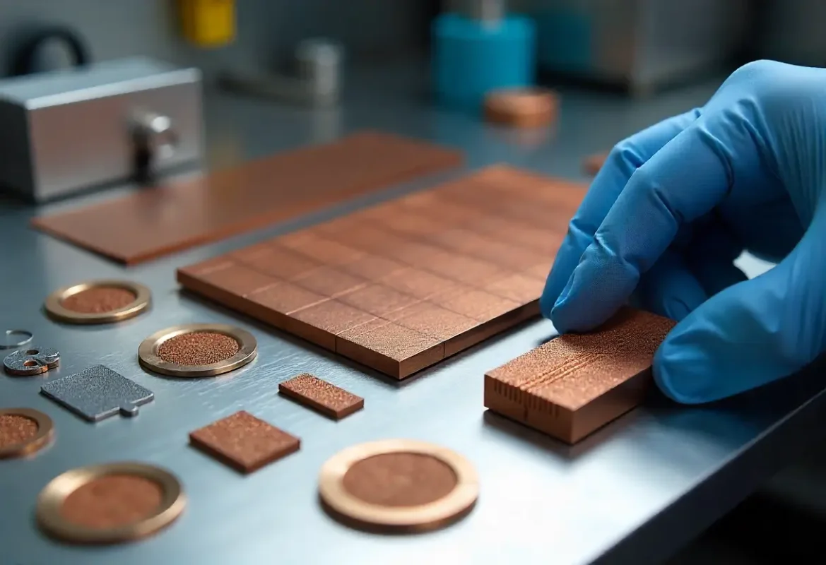
Flatten Hotspots — Improve Reliability
Vapor chambers flatten temperature gradients across a surface, reducing peak junction temperatures and improving component lifetime.

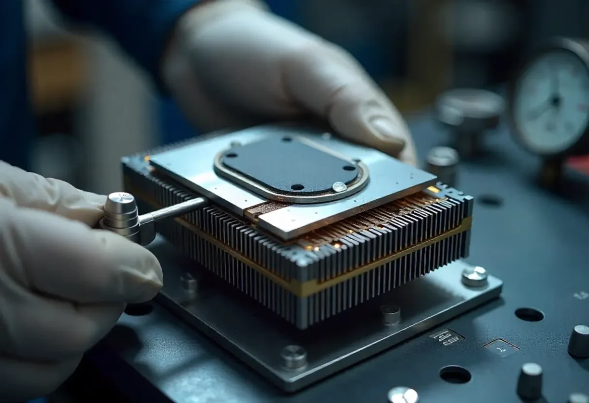
Enable Low Profile Designs
Thin vapor plates (often < 2 mm) allow designs with minimal z‑height while still achieving excellent thermal spreading.

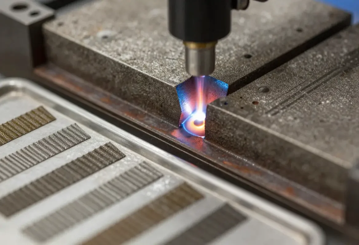
Route Heat Around Constraints
Flattened heat pipes are ideal where a thermal path must be routed around connectors or structural features while maintaining low thermal resistance.
Manufacturing & Fabrication
We fabricate chambers using stamping, rolling, or CNC formed envelopes and produce wicks via sintering, grooving, or composite methods. The working fluid is filled under controlled vacuum and charged to the specified mass and pressure, then sealed via laser welding or brazing. Post‑seal verification includes leak testing and batch thermal sampling.
Process controls
Vacuum bake profiles, fill mass control, seam inspection, helium/vacuum leak testing and batch Rθ sampling to ensure repeatable performance in production.
Integration & Hybrid Assemblies
Vapor chambers and heat pipes are often combined with cold plates, skived heatsinks or housings. We provide brazing, soldering, adhesive bonding, and mechanical mounting strategies to maintain low interface thermal resistance and reliable mechanical fixation.
Assembly options
Brazed interfaces, selective soldering, adhesive bonds with thermally conductive adhesives, and mechanical clamps for serviceable designs.
Materials, Wicks & Surface Treatments
Standard construction uses high‑conductivity copper for chambers and wicks. We offer copper alloys for increased strength or better braze compatibility. Wick choices (sintered powder, grooved, composite) are selected by orientation, heat flux and lifecycle requirements. Plating options (nickel, tin) improve corrosion resistance and solderability.
Environmental considerations
We evaluate galvanic interactions, ambient exposure and coolant environment to recommend barrier coatings or isolation strategies for long‑term reliability.
Representative Geometry & Performance Ranges
Below are typical ranges used as starting points for design. Final values are tuned to your power map, envelope and reliability targets.
Thickness
0.8 — 6.0 mm (vapor chambers); flattened pipes 1.0 — 6.0 mm
Effective Lateral Conductivity
~1,000 — 30,000 W/m·K depending on geometry and wick
Local Heat Flux Capability
>200 W/cm² with tailored wick and vapor paths
Typical Sizes
20×20 mm up to 300×300 mm or custom shapes
| Parameter | Typical Range | Notes |
|---|---|---|
| Chamber thickness | 0.8 — 6.0 mm | Thin for low profile; thicker for rigidity |
| Lateral conductivity | 1,000 — 30,000 W/m·K | Chamber geometry & wick dependent |
| Max local heat flux | > 200 W/cm² | Requires optimized wick and vapor return |
| Operating temp | -40 °C to +150 °C | Working fluid selected to match range |
| Material | Copper / alloys | Nickel/tin plating available |
CFD Correlation & Thermal Characterization
We couple CAD‑linked CFD and conjugate heat transfer simulations with prototype testing to quantify thermal resistance, temperature distribution and transient response. Correlated models shorten iteration cycles and reduce prototype count while giving confidence in production performance.
Deliverables
CFD reports (steady & transient), prototype thermal maps, Rθ measurements and design recommendations for wick and interface selection.
Qualification & Reliability Testing
Typical tests
Leak tests, IR/TC thermal mapping, transient response, thermal cycle and vibration summaries.
Applications

Power Electronics & EV Inverters
Reduce junction temperatures in SiC/IGBT stacks with thin spreaders to meet compact inverter constraints.

Telecom & Datacom
Even temperature distribution across line cards and network modules to lower fan power and improve reliability.

Compute & Accelerators
Vapor plates paired with cold plates for dense rack solutions and accelerator modules.
Representative Projects
EV Inverter Vapor Chamber Integration
22% junction ΔT reduction vs conventional spreader; met 6 mm stack height and passed leak and thermal validation — EVT→DVT→MP in 18 weeks.
Blade Server Vapor Plate
Custom 220×120 mm vapor plate for an accelerator module validated with rack‑level thermal testing and CFD correlation.
Frequently Asked Questions
How thin can a vapor chamber be?
We produce vapor chambers under 2.0 mm for many applications. Achievable thinness depends on required spread performance and handling/assembly constraints.
Do vapor chambers depend on orientation?
Vapor chambers are generally less gravity sensitive than long heat pipes due to the wick providing planar return. For gravity-critical applications we design and test specific wick structures to ensure orientation robustness.
Can vapor chambers be integrated with cold plates?
Yes — we provide brazing, soldering and mechanical mounting options, and validate interface thermal resistance during prototype testing.
Ready to Specify a Vapor Chamber or Heat Pipe?
Upload your power map, geometry and target ΔT. Our thermal engineers will return feasibility notes, wick recommendations and a prototype plan — typically within 24 business hours.